|
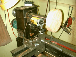
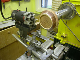
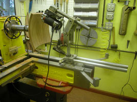
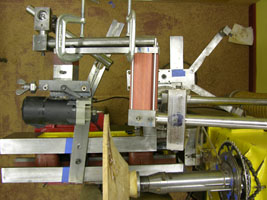
Over the past four years I have been taking pictures of my router
jig, mostly so that I would be able to duplicate the setup if I should want
to make the design again. What it turned out to be I a pictorial record
of the development. The first two pictures in this
folder represents the earliest steel model. The one prior to this was made
from wood and essentially proved the idea feasible.This model had
a steel plate bolted to the lathe bed with a swivel. Having only one bar,
every setup had to be squared off, otherwise the router wasn't square to
the wood. |
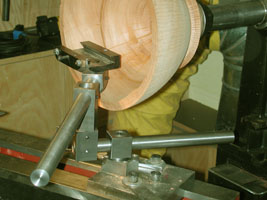
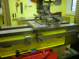
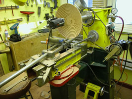
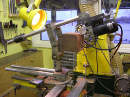
While in retrospect it was a slow processes, I thought it was the best thing
since sliced bread. The setup in this picture permitted me to rotate the
router into the piece. Early features included the extended spindle and
the limiting arms. The slide is a Kelton product. All the steel is 1/2"
thick and the bars are 1" diam. I realized early on that vibration
is a problem and massive steel will dampen it. I turned the piece by hand
as the slowest speed of the lathe was too fast and created a lit of vibration.
The first two photos were taken 12/01 |
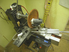
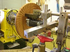
7/02
In the second model I rebuilt the jig to have two bars, eliminating the
squaring problem and adding rigidity. I also added needle bearings and
increased the bearing area of the swivel. I have always wanted to make
spirals. this was one attempt. If you follow the wire it is essentially
a series of pulleys. While it ALMOST worked, I couldn't get the consistency
I wanted and concluded it was a dead end.
|
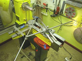
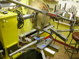
4/03
There are a lot of changes here, mostly that I am in my new shop. I have
added a low speed drive so that I didn't have to turn the piece manually.
That proved to be the most revolutionary change. No more carpal tunnel
syndrome. Also vi sable above the spindle is a small bent bar. Skip ahead
a few frames to see its function.
I again was experimenting with spirals. This one included a gear box below
the horizontal disk. While again it ALMOST worked, there was to much accumulated
play and the consistency wasn't there. |
4/03
Also vi sable is a new indexing head. giving up to 96 divisions. Up until
this point all my pieces were symmetrical about the center line of the lathe.
Here was an attempt to move the swivel point off center. This required a
lot of backing and forthing between beds and locations on the same bed,
which gave me the idea to redo the bed, and provide access from the side.
This modification will visible latter. You will also notice that the lathe
is no longer black. |
It
became obvious that relocating the jig "about" where it was
was not sufficient to get the results that I wanted. The answer was setting
up a indexing system on the bed enabling me to come back to a point. This
is the result.
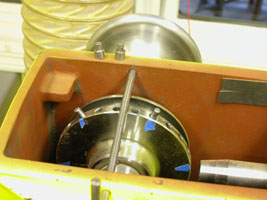
A
word about the lathe. It is a Stubby 1000 that I bought from John Jordan.
No other lathe would have enabled me to bo this kind of work. The
movable bed with the side bed is critical. |
In
addition to being able to divide the piece into a number of segments, I
also wanted to be able to control the starting point. this gizmo allows
me to move the starting point as little as .001" |
This
is one of the earliest modifications that I made to the lathe. It is visible
in the 7/02 photo and it permitted me to make horizontal cuts. If you go
to my early folders the results should be obvious. By using different size
pegs I am able to control the spaces between the cuts. |
8/03
Here is where it starts getting REALY serious. Up until this point all my
cuts were on the x-z axis. Left, right, in, out. By raising my pivot point
from the bed of the lathe to the center point I am now able to make cuts
off center, that is on the "y" axis. This was the most difficult
fixture I designed. Accuracy, rigidity, clearances and versatility all had
to be accommodated. It was too expensive to have to redo it. Fortunately
I know an excellent machine shop with exacting machinists. this wouldn't
have been possible otherwise. |
10/03
Any thing worth doing is worth doing to excess. This little fixture permits
me to make cuts behind the face. While the idea worked, I was not particularly
impressed with the aesthetic results. The idea will resurface in latter
pieces with different uses. Also notice the tie rod at the tail end of
the bar. With this I can now control the elevation to very close tolerances.
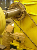
A
word about the chain and sprockets. Not knowing what the optimum speeds
would be I purchased a bunch of them and experimented over time and came
up with the best speed. |
6/04
One more time. This turned out to be a real "Rube Goldberg." Turning
the crank turned the screw which wound up the cord and pulled the router
across the face of the piece while turning the bowl. I made all the parts
from plexiglas. Alas, while it again worked reasonable well, the control
wasn't there and I wasn't particularly impressed with the design. My wife
tells me, continuously, "Just because you can, doesn't mean that you
should." These parts ended up with the rest, in a draw. |
12/04
Before was serious, this is interesting. Up until this point all the cuts
were straight, or sometimes spirals. The idea came to me that the cuts didn't
have to be straight. I jerry rigged this setup to test the idea. I cut and
shaped a piece of plastic and bolted it to my tool rest. By placing it at
the proper height I was able to draw the cutting bar across it and produce
the wiggly line. This of course opened up a whole new avenue of exploration,
with lots of possibilities, which I currently am in the middle of. |
12/04
The problem with the previous setup was that the location of the tool
rest interfered with the router. This setup, with the addition of a few
more parts, resolved it. By moving the location of the template forward
or backward I am able to control the severity of the curve.
A
word about the "z" (in, out) axis control. It is a 1/4-20 screw
which gives me .050" per revolution. The nut is numbered so that
I can keep track or turns. Moving one number gives me .008" travel
Most of my pieces require that kind of precision. |
12/04
I have developed two basic shapes, concave and convex. The previous setup
was for the concave design. The convex form created another set of problems,
because the pivot point was behind the working face. This problem appeared
similar to the solution four frames back but the geometry is very
different. This is the jerry rigged version of the solution. The object
was to get the cutter around the rim onto the face and locate the pattern
in a place it didn't interfere with the movement. Another problem was
the location of the stops. |
This
is a top view of the setup. From this view the relationship of the pivot
point to the face is more visible and the temporary nature of the setup
is obvious. The result of this particular setup is a piece that I am calling
"Yellow Brick Road" that can be seen in the
05-1 folder. |
01/05
The idea here was to make a closed form with spherical sides. I then moved
the pivot point back and cut flutes into the four sides. by moving the
pivot point back I flattened the curve. the results can also be seen in
the 05-1 folder. It also filled in time while parts were being made.
|
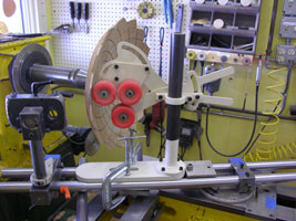
02/05
This is the "hardened" version of the setup two frames ago. I'm
Sorry for the fuzziness of the picture. There are quite a few changes. One
is the heavy duty arm which is necessary to reduce vibration. Another is
the follower arm. A third is the cutter pivot assembly. This permits me
to adjust the angle of the cutter relative to the surface of the piece.
By far the new indexing head is the best. The bike chain is gone and replaced
with #25 chain. It has a low profile 4" ball bearing race and three
separate indexing rings, 48, 60 and 63. This gives me lots of odd numbers
and .000" play. |
Finally
my spirals. The answer was in the indexing head and the linkage. Both
ends of the connecting rod had to rotate universally, with zero play,
and the length had to be adjustable. The holes in the swing arm will be
replaced with a slot so the length can be micro adjusted. That need became
apparent in the making of this piece. I wanted to get the outermost line
crossing a little further out, but couldn't.
|
Ray
Leier of the delMano Gallery suggested that I make my pieces larger. Up
until that point most of what I was doing was 12" in diameter. These
last few pieces are 15". This is the largest that I can make.
Besides the vibration issues increasing exponentially the issue of warping
is back. I thought I had it solved with kiln dried wood, but at 15"
it's back. This was my solution. I had purchased this One Way fixture a
while ago, you can see it hanging on the wall in the previous frame. It
locks the piece between the cutter and the wheel, maintaining the relationship. |
Sample Text |